130 Vdc Motor Wiring Diagram
PowerWise Systems Manuals wiring diagrams. RockReady Review 1977 K-5 gets Hehr Power on board welder.
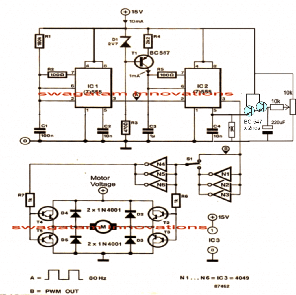
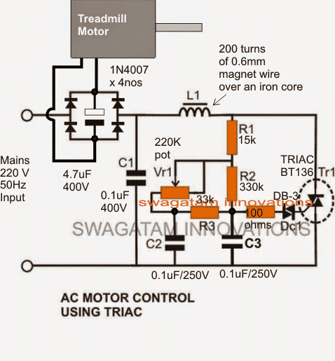
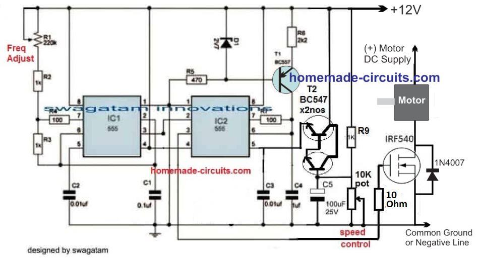
Treadmill Motor Speed Controller Circuit Homemade Circuit Projects
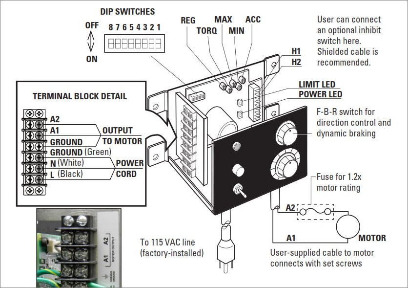
Filtered DC Motor Speed Controls.

130 vdc motor wiring diagram. Repair Manuals Service Manuals Workshop Manuals ECP Diagnostics. Lv429389 Mx Shunt Release Compact Nsx Rated Voltage 525 Vac 50 Hz 600 60 Schneider Electric Global. Where can I find single phase electric motor wiring diagrams.
Instant workshop manual download. Wiring Diagram for AC DC Inc. All the top makes.
AC80 AC90 AC100 single phase motors. Abb S5n Breaker Wiring Second Life Storage. Variety of john deere l130 wiring diagram.
Hehr power systems 10-130 wiring instructions D301217X012 ROC800-Series Remote Operations Controller. I have compiled a group of single phase internal electric motor wiring diagrams and terminal connections below. Trucks 4x4.
4 wire reversible PSC motor with a triple pole double throw switch. Tm 8112 Circuit Breaker Shunt Trip Wiring Diagram. MINIMUM SUPPLY WIRE SIZE REQUIREMENTS Minimum Size Wire AWG Cu Only Maximum Motor Current DC Amps Maximum Motor HP 90 V Maximum Motor HP 180 V Max 50 Foot Run Max 100 Foot Run 6 05 1 16 14 12 1 2 14.
Use figure 1 if your motor has a single voltage shunt field. You ve broke on a trail and need some welding work done to get home ADD YOUR BUSINESS. Always use wiring diagram supplied on motor nameplate.
Wiring for Instrument Panels with Transmission Pressure Gauge. For cooler motor operation longer brush life. Ad Online Chat Support.
AS-183 wiring diagram with switch. 5 fExamples of Control Circuits 2- and 3-Wire Control Elementary Diagrams Low Voltage Release and Low Voltage Protection are the basic control circuits encountered in motor control applications. Motor Wiring Diagram DC.
GENERAL CONNECTION DIAGRAM Sh M Ol 5 2 SAFETY WARNING. Some text links below go to applicable products on Amazon EBay and Northern Tool and Equipment. After Market Panels Wiring.
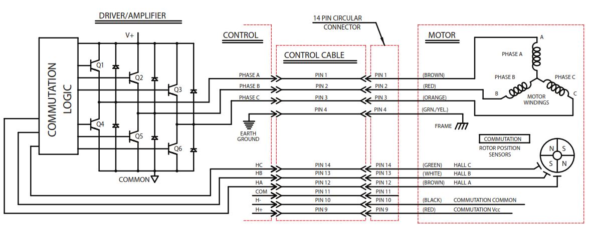
Motor Connections Your motor will be internally connected according to one of the diagrams shown below. Click on the image to enlarge and then save it to your computer by right clicking on the image. 0-130 VDC Form Factor.
2-11 in which vector 1 is 120 degrees in advance of vector 2 and the phase sequence is 1 2 3. TERMINAL MARKINGS AND INTERNAL WIRING DIAGRAMS SINGLE PHASE AND POLYPHASE MOTORS MEETING NEMA STANDARDS See Fig. All the top makes.
John Deere L130 Belt Diagram John Deere L120 Clutch Wiring Diagram. At the bottom of this post is also a video about DC shunt motors. It appears that I have the AC input wire s and DC ou tput wires installed correctly a ccording to t he users manual for the motor driveI placed a 10K ohm potenti ometer on the motor drive per the.
Here is a basic wiring diagram that applies to all Vintage and Antique Lawn and Garden Tractors using a Stator Charging System and a Battery Ignition System. 3 WIRING DIAGRAMS 1 WIRING DIAGRAMS Diagram ER9 M 3 1 5 9 3 7 11 Low Speed High Speed U1 V1 W1 W2 U2 V2 TK TK Thermal Overloads TWO SPEED STARDELTA MOTOR Switch M 3 0-10V 20V 415V AC 4-20mA Outp uts Diagram IC2 M 1 240V AC 0-10V Outp ut Diagram IC3 M 1 0-10V 4-20mA 240V AC Outp uts These diagrams are current at the time of publication. 208230 VAC line input to provide 0-130 VDC with a 115 or 208230 VAC line.
Connections for optional user-supplied inhibit switch available Filtered DC Output. 10 Inhibit Function. See MG 1-221 MG 1-224 Direction Of Rotation.
Instant workshop manual download. 0-130 0-240 VDC 2 AMPS I attempted to wire everythi ng up this evening and cannot get more than 5 vol ts DC out of the outputs for the motor drive. WIRING DIAGRAMS - STANDARD MOTORS N 3 WIRING DIAGRAMS 1 WIRING DIAGRAMS Form A M 3 M 3 High speed delta connection Low speed star connection W2 or White W2 or White U2 or Black U2 or Black V2 or Orange V2 or Orange U1 or Red U1 or Red V1 or Yellow V1 or Yellow W1 or Blue W1 or Blue Thermal Contacts TB White.
The simplest schemes are shown below. Panels _ 2016 Version. Ad Online Chat Support.
Repair Manuals Service Manuals Workshop Manuals ECP Diagnostics. Non-Programmable General Distribution of Engine DC. Variable Ratio Tachometer Programmable vs.
This applies to all old Cub Cadet Ford Jacobsen John Deere Wheel Horse Case and Simplicity Garden Tractorsnbsp. So you want an ON BOARD WELDER. WPM Connection Diagram NEMA-1 All wires external to control must be supplied by user This fuse should only be.
Qou3701042 mini circuit breaker qou 70a 3 pole 240 vac 10ka shunt trip schneider electric canada how do you wire the on a edb faqs us to nader qob1201021 qo 20a 1 120 10 ka bolt mount ac usa motor mechanism diagram wiring full version hd quality pocdiagram arsae it a9n26946 mx plus of 220 415vac dc global Read More. 12 Position Terminal Wiring Diagram for AC DC Inc. Wiring Diagram For John Deere 212 Fresh Wiring Diagram For John.
We did our best to keep this as simple and as easy to understand as possible. 115230 VAC 4 AMPS 60 HZ ARMATURE. Magnetic Pickup Tachometer vs.
This form of electrical diagram is sometimes referred to as a schematic or line diagram. These connections are in accordance with NEMA MG-1 and American Standards Publication 06. 33661 Mx Shunt Release Compact Ns630b To Ns3200 Fixed Masterpact Nt Nw Rated Voltage 100 130 Vdc Vac 50 60 Hz Schneider Electric Global.
Use figure 2 if your motor has a dual voltage shunt field.

How To Make A Coil Winding Machine Using 48 Volt Dc Motor And Dc Motor Speed Con Lagu Mp3 Mp3 Dragon

Pin On Tool Ideas
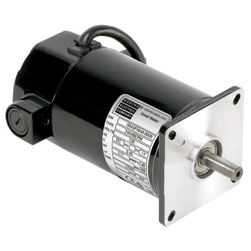
Bodine Electric 0047 Dc Motor 1 17 Hp 130vdc 2500 Rpm
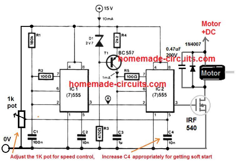
Treadmill Motor Speed Controller Circuit Homemade Circuit Projects

17 Car Horn Relay Wiring Diagram Auto Mecanica Fiacao Eletrica Auto
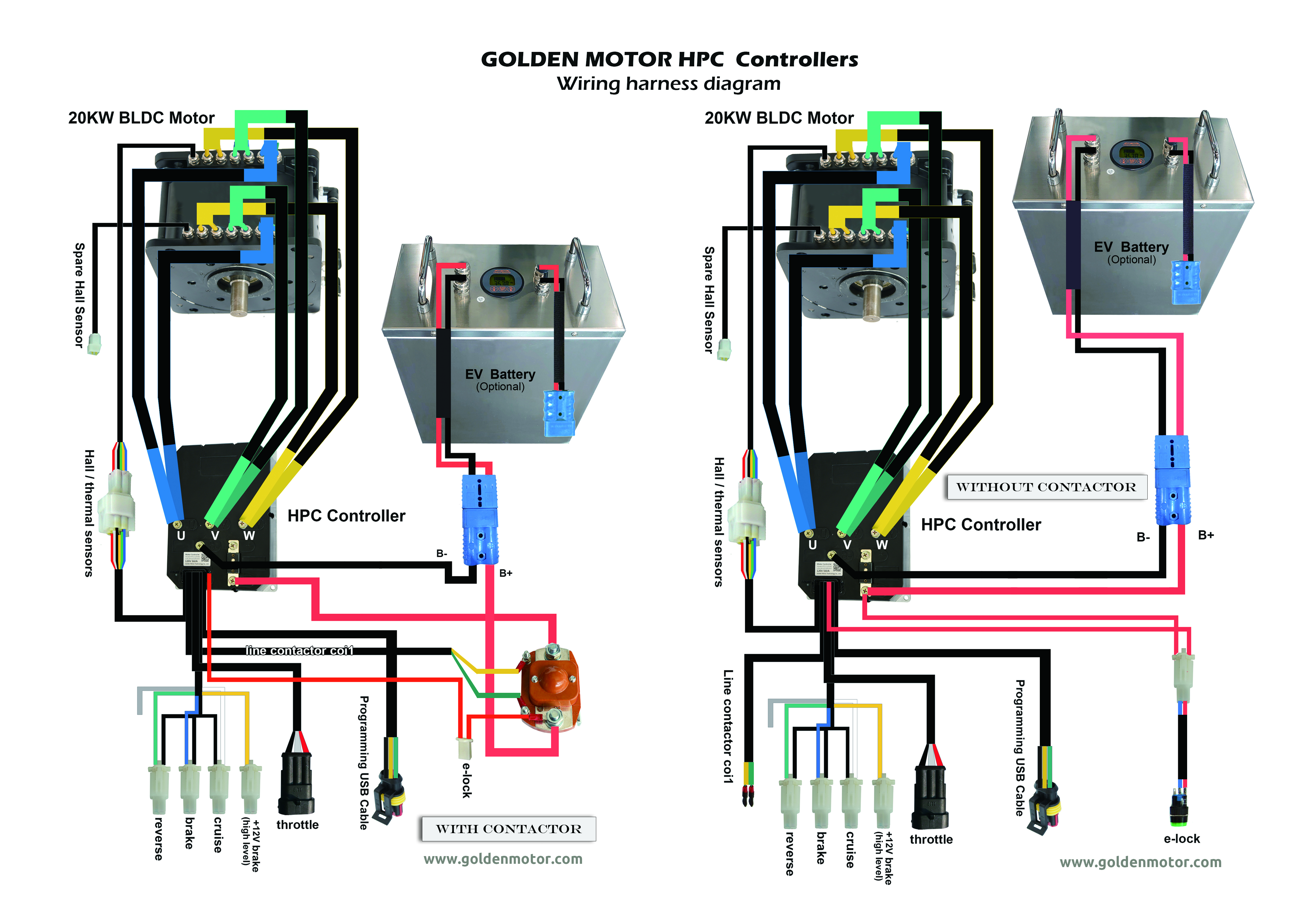
Brushless Motors Bldc Motor Sensorless Motor Motor Controllers Foc Controller Field Oriented Control Brushless Motor Controller Bldc Controller Axial Flux Brushless Motor Golden Gmx
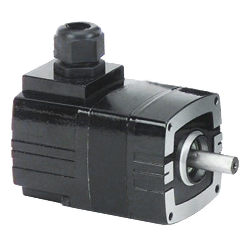
Bodine Electric 3314 Dc Motor Brushless 1 5 Hp 130vdc 10 000 Rpm
Introduction To Brushless Dc Ec Motor And Gearmotor Technology Bodine Gearmotor Blog

130v Dc Motor Control Electrical Engineering Stack Exchange
Treadmill Motor Speed Controller Circuit Homemade Circuit Projects

Dc Motors Gearmotors Motors
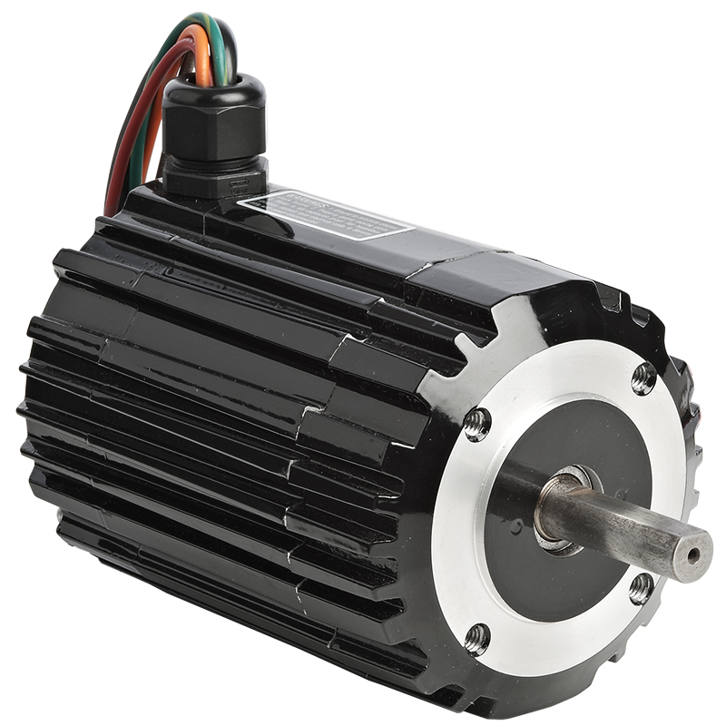
Bodine Electric N3406 Dc Motor Brushless 1 5 Hp 130vdc 2500 Rpm

22 Stunning Electrical Switch Wiring Diagram Bacamajalah Electrical Circuit Diagram Electrical Wiring Diagram Electrical Switch Wiring
Treadmill Motor Speed Controller Circuit Homemade Circuit Projects
How To Build A High Torque Dc Motor Speed Controller Circuit Bright Hub Engineering
Treadmill Motor Speed Controller Circuit Homemade Circuit Projects
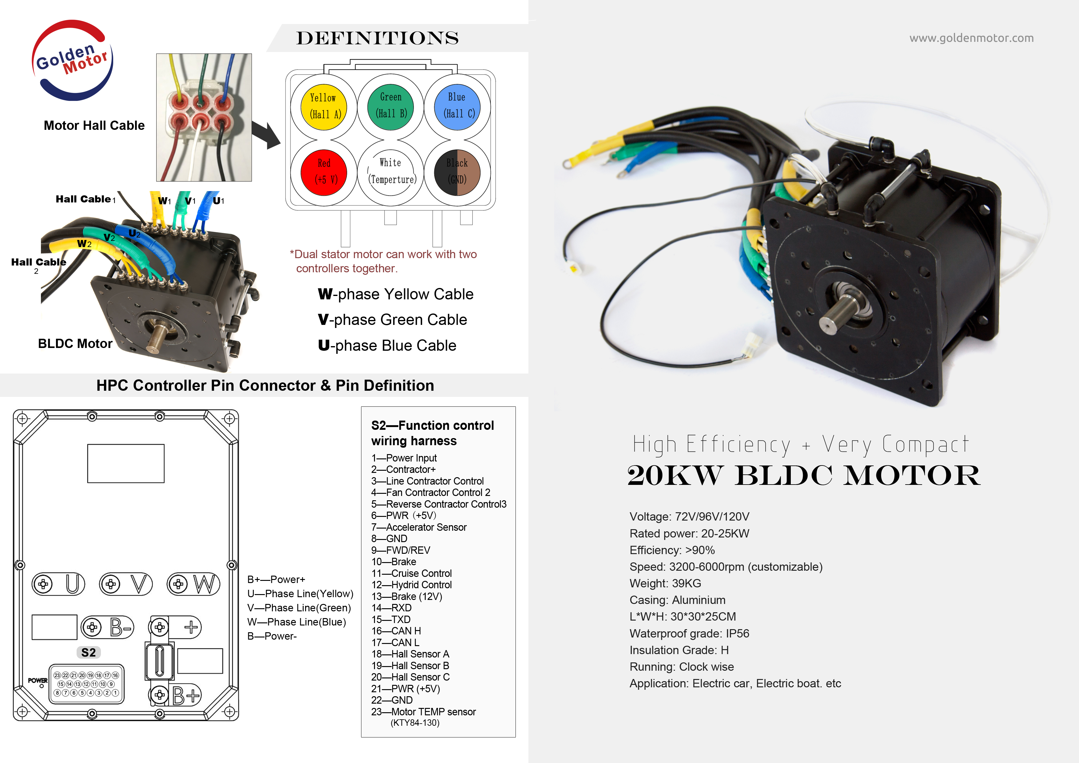
Brushless Motors Bldc Motor Sensorless Motor Motor Controllers Foc Controller Field Oriented Control Brushless Motor Controller Bldc Controller Axial Flux Brushless Motor Golden Gmx
New Dc Motor Speed Control With Dynamic Braking Bodine Gearmotor Blog

How To Build A High Torque Dc Motor Speed Controller Circuit Bright Hub Engineering