Hornby Dcc Wiring Diagram
This is the wire that we supply in all of our DCC starter wiring kits and on our pre-wired rail joiners. Here is a picture gallery about hornby dcc wiring diagram complete with the description of the image please find the image you need.

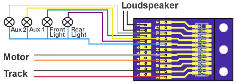
Pin On Layout Plans
Traditionally this should be connected to the pickups that collect power from the RIGHT rail That is right from the loco driver point of view.

Hornby dcc wiring diagram. 22092018 22092018 7 Comments on Hornby Dcc Wiring Diagram Fitting A standard Hornby 4-Function decoder into a Hornby Steam train Class BF12 from the Anglian Box Set. Basic point wiring diagram with Hornby R044 passing contact switch. Remove the plug from the chip.
Were working on a short tutorial looking at DCC decoder installation in older locomotives such as Lima and Hornby that are powered by ringfieldpancake-style motors. Decoder installation guides hornby dcc wiring diagrams for non diagram tcs a general guide to reverse loops in loconet bachmann full converting layout welcome demonstrating the elite class 66 dccconcepts modelling advice turnout motors dccwiki digital command control model rail forum loco blacklist points turnouts advanced 7 point part 2 1 solenoid basics limited edition train. Note how all the connections are either red or black and therefore can be joined into a total of two wires see the two wire myth in part 1 On DC control most of the red connections would have to be separately wired back to individual switches on the control panel.
Continue reading DCC Decoder. R351 Thomas the Tank Engine 0-6-0 R782 0-4-0 Smokey Joe. Peco PL-13 accessory switches fit directly onto Hornby point motors without modification and can be used for frog switching on live frog points such as Peco electrofrogs points operated signalling to provide feedback for automatic control or just to indicate on a control panel that the point has.
There is no wiring diagram and different models have different wiring patterns Not helped by Hornbys habit mixing configurations between common negative and common positive and having all black wiring What is in your favour is that the resistors are all mounted on the board so the chances of damaging an LED are slim. Please remove or cut themhigh Thats it - just wires to attach now. Traditionally this should be connected.
Hornby Point Motor Wiring Diagram wiring diagram is a simplified okay pictorial representation of an electrical circuit. It shows the components of the circuit as simplified shapes and the facility and signal associates amid the devices. Step 2 -attach the droppers 1 Attach the green wire to the frog.
We believe that DCC should make it easier to build control and use model railways so all of our range of DCC Signals Controllers and accessories connect using just 2 wires and are all setup using just a single button press which we call One-Touch DCC. Step-by-step guide wiring diagram. They cover the more modern can-style motors as found.
BLACK WIRE this is also to pick up power from the track. 2 Attach the other 2 wires. Solder Grey Orange wires.
Were working on a short tutorial looking at DCC decoder installation in older locomotives such as Lima and Hornby. Think fitting DCC Decoders is difficult to older models without a DCC Socket. A simple wiring diagram has been provided by Hornby to help you make the connections in your locomotive.
Hornby DCC decoder wiring guide. RED WIRE this is to pick up power from the track. Class 67 Dcc Sound And Lighting Update Inside Hornby Dcc Wiring with Hornby Dcc Wiring Diagram image size 800 X 286 px and to view image details please click the image.
DCC WIRING CLINIC 11 Basic Plain Track Wiring for DCC Track Feeders 20 24 gauge stranded Track Bus Wires. R9064 Diesel R9046 Toby the Tram. Its important to remember that you should take your time in doing this to avoid damage to the locomotive electrics body and chassis.
DCC Installation Guides - Specific Products. Hornby Dcc Wiring Diagram Mar 13 Were working on a short tutorial looking at DCC decoder installation in older locomotives such as Lima and Hornby that are powered by. Ky 7560 Hornby Dcc Decoder Wiring Diagram Schematic.
Solder Black Red wires from chip one to each pick up wire. Wiring Diagram Digital Command Control Electrical Wires Cable Electric Motor Png 1036x727px Area. Connect it to the common terminal of one of Cobalts built-in -power SPDT switches.
10 gauge 14 gauge solid conduit wire 14 gauge more than sufficient for 100 feet run in HO 3 feet OK between feeds closer on smaller code track. Locate the wires from the pick ups and remove from motor. To accompany the tutorial weve produced a PDF containing a series of basic wiring diagrams to help with the installation process.
R852 James R9070 Oliver R9097 D7101. Solder rail joints between feeders andor at least one feeder each rail length. An example wiring diagram for a basic layout is shown below and you can see how the basic rule is applied.
Digital commands down 2 wires or rails to control and power locomotives and accessories. A Hornby loco and decoder can be operated by Bachmann DCC console or a The most simplest layout can be wired for DCC by using two wires from the. Gapped but there will be wire links here.
If you want to find the other picture or article about Hornby Point Motor Wiring. R2675 RailRoad Flying Scotsman. Follow our step by step guides to see just how easy fitting a chip can be.
Wiring For Dcc By Allan Gartner Track Switches Digital Command Control Of Model Trains Using Freindly. In general the wiring of each circuit and loco follows the following basic principles. This works on the assumption that even a 3ft long piece of rail may have up to 2 locomotives working on it and modern OO gauge locomotive motors are unlikely to.

Rr Train Track Wiring Rail Vacation Travel Information Modeltrainsets Model Trains Model Railway Track Plans Train
This Is A Faithful Recreation Of Plan 15 From The Little Book Of Track Plans Published By Peco It Model Railway Track Plans Model Train Layouts Model Trains

Wiring For Dcc By Allan Gartner Track Switches Wiring For Digital Command Control Of Model Trains Using Dcc Fre Model Trains Model Railway Track Plans Train
Hornby Fried Sound Chip

Model Trains Preparation Is Definitely The Most Crucial Action In Constructing A Model Railroad For Your Model Model Train Layouts Train Layouts Model Trains

Hornby Oo Gauge Track Layouts Google Search Hornby Gauges Layout

How To Wire A Layout For Dual Cab Control Using An Atlas Controller And Selectors Ho Model Trains Ho Scale Train Layout Model Railroad

Rr Train Track Wiring Automatic Reversing Loop Conrol For Dc Dcc Or Ac Dogbone Layout Model Trains Ho Model Trains Model Train Sets

7x5 Mixture Of Hornby And Peco Parts For Maximum Operational Potential It Has A Station Turntable Goods Y Model Train Layouts Ho Model Trains Train Layouts

Train Tracks Pts Diagram Model Train Control System Diagram Model Train Control Programs G Z S Model Trains Model Train Layouts Train Layouts

Pin By Warren J Mcclure Ii On Ho Scale Trains Layouts Scenery Rolling Stock Model Trains Model Train Layouts Train Layouts

Turntable Conversion Hornby Model Train Layouts Ho Model Trains Model Train Sets

Free Track Plans For Your Model Railway Model Trains Model Train Sets Model Railway

How To Use Dual Cab Control To Power And Operate A Turntable And Turntable Motor Using An Atlas Controll Ho Model Trains Ho Train Layouts Ho Scale Train Layout

Turntables Model Train Layouts Model Trains N Scale Model Train Layouts

Twin Loop Wiring With Relay Model Train Layouts Model Railway Track Plans Model Trains

Hand Laid Points Ruchnaya Ukladka Strelki Ho Model Trains Model Train Layouts Model Trains

Example Railway Signaling Model Train Layouts Model Trains Ho Scale Train Layout

How Do I Hard Wire Hornby Dcc Decoders Into A Locomotive The Island Railway Shop