Micro Motion 2700 Wiring Diagram
Micro Motion Wiring Diagram. IECEx Certificate F H R CNG050 Micro Motion.

Single Ds18b20 Temperature Sensor Wiring Diagram Wired Sensor Temperatures Arduino
Ensure the instrument pole extends at least 12 in 305 mm from a rigid base and is no more than 2 in 51 mm in diameter.

Micro motion 2700 wiring diagram. If desired re-orient the transmitter on the mounting bracket. This chapter describes how to install Micro Motion Model 1700 and 2700 transmitters. Micro Motion 1700 and 2700 Field and Integral Mount Transmitter Overview Powered by MVD Technology these versatile field-mount transmitters are built with an advanced architecture and provide a wide variety of I O and application flexibilities making them the.
2700 1 G Mounting code. Micro Motion 1700 and 2700 Field and Integral Mount Transmitter Overview Powered by MVD Technology these versatile field-mount transmitters are built with an advanced architecture and provide a wide variety of I O and application flexibilities making them the. Determine the location of the transmitter and other flowmeter components see Section 22 Mount the transmitter see Section 23.
Drawings Schematics Wiring Diagram. Drawings Schematics. Drawings Schematics Wiring Diagram.
Maximum wire lengths are. 2700 PROFIBUS PA Micro Motion PDF. Connect the shield wire to the ground screw.
Drawings Schematics. 531 Safe area mA output wiring The following 4. Output Wiring Model 17002700 Intrinsically Safe Transmitters Safe area output wiring The following notes and diagrams are designed to be used as a guide for wiring the Model 1700 or Model 2700 outputs for safe area applications.
Drawings Schematics. DS600 JBOX 1700C-2700C Micro Motion PDF. Micro Motion does not supply U-bolts or nuts appropriate bolts and nuts are available as an option.
Determine the location of the transmitter and other flowmeter components see Section 23 Mount the transmitter see Section 24. Drawings Schematics Wiring Diagram. 2700 PROFIBUS PA Micro Motion PDF.
2700 PROFIBUS PA Micro Motion PDF. Determine the location of the transmitter and other flowmeter components see Section 23 Mount the transmitter see Section24 Mount the core processor if. Enhanced Core to 1500-2500D Micro Motion.
DS600 JBOX 1700C-2700C Micro Motion PDF. The following general steps are required. CORE TO 3500 Micro Motion PDF.
Application Manual Sensor installation manual Before you begin Installation Manual September 2020 MMI-20027478. 300 ft 100 m of 22 AWG 035 mm 1000 ft 300 m of 18 AWG 08 mm Connect the four color-coded wires or shielded 2-wire cable wires to the numbered core processor terminals. 34 Micro Motion Model 1700 and 2700 Tran smitters Output Wiring Model 1700 2700 Intrinsically Safe T ransm itters 53 Safe area o utput wiring The following notes and diagrams are design ed to be used as a guide for wiring the Model 1700 or Model 2700 outputs for sa fe area applications.
This video details how to integrate the Emerson Micro Motion 5700 Coriolis meter into a PLC with Rockwell software. Enhanced Core to 1500-2500D Micro Motion. The following general steps are required.
CORE TO 3500 Micro Motion PDF. Drawings Schematics Wiring Diagram. This chapter describes how to install Micro Motion Model 1700 and 2700 transmitters.
Drawings Schematics Wiring Diagram. DS600 JBOX 1700C-2700C Micro Motion PDF. This chapter describes how to install Micro Motion Model 1700 and 2700 transmitters.
Drawings Schematics. Mounting and sensor wiring for 9 wire remote installations figure 4 2. 531 Safe area mA output wiring The following 420 mA wiring diagrams are examples of proper basic wiring for the Model 1700 mA output or Model 2700 primary.
Externally Powered Discrete Input Wiring 2. Micro Motion 5700 Transmitters with a Marine Bunker Transfer Package. The following general steps are required.
R 4-wire remote mount I Integral mount B 4-wire remote mount to 9-wire remote core processor C 9-wire remote mount Display code 1 Display with glass lens 2 Backlit display with glass lens 3 No display 5 Backlit display with IIC approval glass lens. Drawings Schematics Wiring Diagram. 6 Micro Motion 5700 Transmitters with Configurable Inputs and Outputs.
2700 PROFIBUS PA Micro Motion PDF. DS600 JBOX 1700C-2700C Micro Motion PDF. CORE TO 3500 Micro Motion PDF.
This video applies to RS software version 20 and above. Drawings Schematics Wiring Diagram. Enhanced Core to 1500-2500D Micro Motion.
Micro Motion 1700 and 2700 Field and Integral Mount Transmitter Overview Powered by MVD Technology these versatile field-mount transmitters are built with an advanced architecture and provide a wide variety of I O and application flexibilities making them the. ProLink II Basic information on ProLink II is provided in Appendix F. CORE TO 3500 Micro Motion PDF.
Configuration and use manual mmi 20019043 rev ab march 2018 micro motion model 2700 transmitters with analog outputs configuration and use manual.

Wind Turbine Wiring Diagram Wind Turbine Generator Wind Power Generator Wind Turbine

New Bmw E46 318i Ecu Wiring Diagram Bmw E30 Wiring Diagram Bmw

18 Electric Mobility Rascal 255 Wiring Diagram Wiring Diagram Wiringg Net Diagram Wiring Diagram Rascal Scooter

18 Gmf Electric Motor Wiring Diagram Wiring Diagram Wiringg Net Electric Motor Wiring Diagram Wiring Diagram Diagram
Diagram Gm Wiring Harness Diagram For Pcm Full Version Hd Quality For Pcm Mediagrame Teatrodelloppresso It

Painless Wiring Diagram Wiring Diagram Diagram Wire
Wiring Schematic For Razor E100 In 2021 Baseboard Heater Thermostat Thermostat Wiring Baseboard Heater

Diagram Mag Ic Electrical Switches Wiring Diagram Full Version Hd Quality Wiring Diagram Rediagram Amicideidisabilionlus It
Emerson Micro Motion 2700 Installation Manual Pdf Download Manualslib

Dvi Pinout Wiring Wiring Diagram Detailed Dvi Electronics Lab Wiring Diagram
Diagram Highway Wiring Diagram Full Version Hd Quality Wiring Diagram Cpudiagram Segretariatosocialelatina It
Diagram Deh 15ub Wiring Diagram Full Version Hd Quality Wiring Diagram Diagramhs Segretariatosocialelatina It

White Motion Sensor Wiring Diagram Sample Motive Ideas Lighting Decoration Themes Adjustable Electronic Gif Resize D336 2 Motion Detector Wiring Diagram Sensor

Es200 Wiring Diagram Connection Scheme In 2021 Wiring Diagram Automatic Sliding Doors Diagram
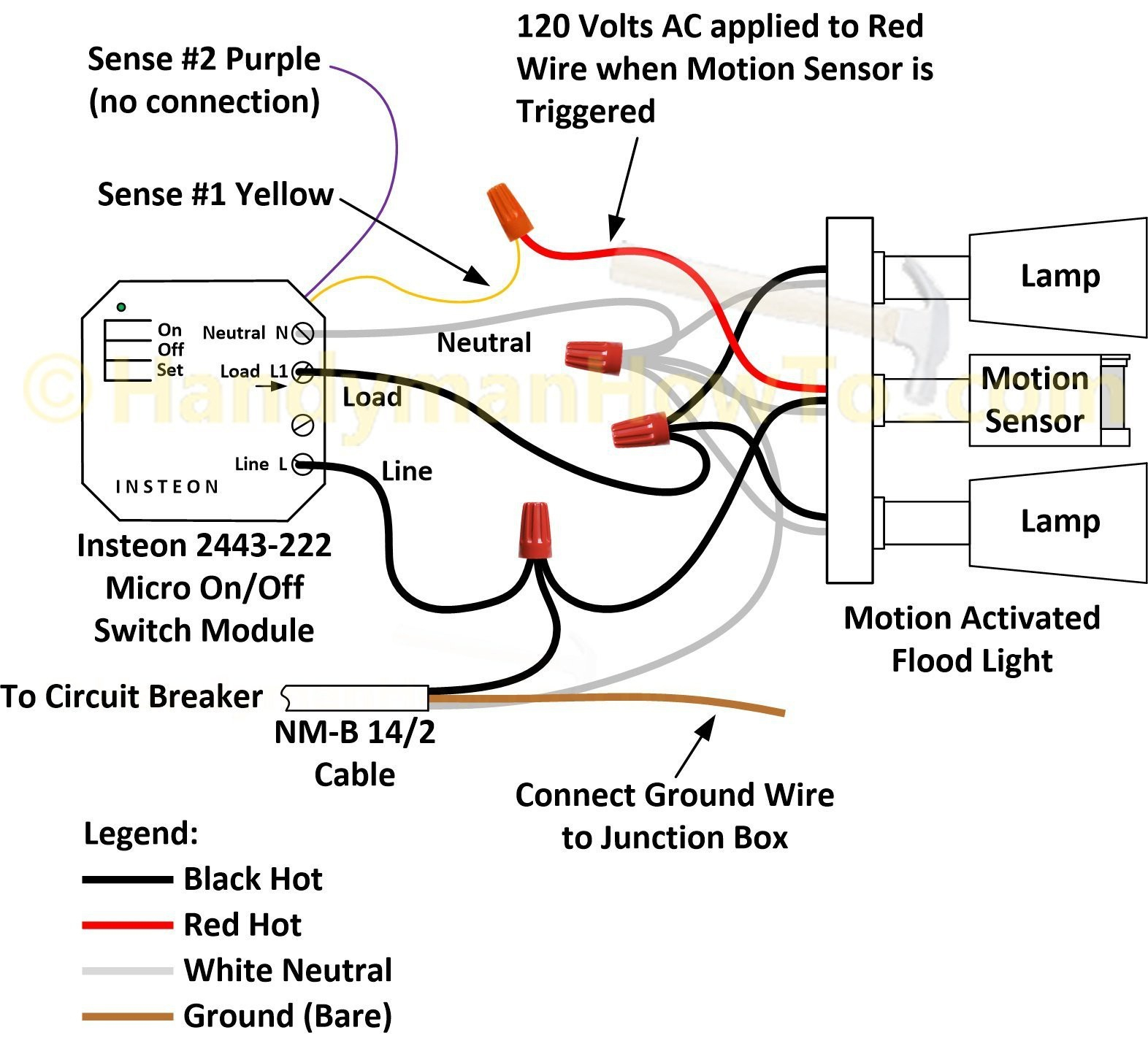
Diagram Occupancy Sensor Wiring Diagram 3 Way Full Version Hd Quality 3 Way Lendiagram Amicideidisabilionlus It

Rapidlogger Oilfield Support Tech Note 62

Diagram R6 Ecu Wiring Diagram Full Version Hd Quality Wiring Diagram Dmdiagram Amicideidisabilionlus It

Diagram 1995 Lincoln Town Car Stereo Wiring Diagram Full Version Hd Quality Wiring Diagram Adiagrams Amicideidisabilionlus It

Emerson Micro Motion 2700 Installation Manual Manualzz